Supporting the Search for Design Solutions Based on Information Recognition and Automated Classification
H. Grabowski, S. Rude, C. Liu, K. Hain
Institut für Rechneranwendung
in Planung und Konstruktion (RPK)
Universität Karlsruhe, D-76128 Karlsruhe
Saving the ability to compete imposes todayës enterprises with the problem, to develop products with higher complexity and quality in shorter periods of development and by causing fewer costs. In contradiction to these requirements the periods and costs of development increase because of the customers requests /Milb-91/. A quick search and usage of existing, reliable design solutions could be seen as a support to solve these problems. Re-using already existing parts and assemblies in terms of solutions for specific problems can support the reducing of the variety of products, ensures the use of guaranteed knowledge and reduces the time of product development. The analysis of part- and product spectrums showed a re-use ratio of 10 % for engineering parts and 40 % for manufacture facility parts /Dirz-72/. Main requirements for a goal-oriented efficient use of existing design solutions is that "old" design solutions are available in a form computers can process with and the problem-conform compression of information through a computer-based product classification. Research on the subject of finding existing design solutions has to concentrate on the area of information recognition and product classification, in the course of which the primary goal is the complete support of the design process.
The introduction of new parts increases the variety of variants and the complexity of products of the enterprises. A case-study of Wildemann /Wild-94/ shows the variety and therefore the complexity using a depiction of the number of parts, assemblies and products within the last twenty years (fig. 2.1). One can see a tripling of part identification numbers due to increasing customer requirements and the necessity to produce more and more variants. The result is a decrease of turnover per part identification number of 40 % (from 100 % to 60 %) caused by product variety.
Therefore, a main goal has to be the re-use of existing design solutions to reduce the variety, complexity and costs and to find potential for rationalization. The pressure to re-use, standardise and clear up the product spectrum has to start in the design departments, because this measures cause rationalization of courses in following areas like production scheduling or production e.g. by forming of part families. Because re-using of existing design solutions prevents the development of new parts, the expenditure for introduction, administration, use and finally discontinuation is dropped. Various investigations revealed life-cycle-costs of a newly introduced part from 10.000 DM to 28.000 DM /Made-92, Hich-86/. Therefore, the introduction of new parts needs always to be verified for costs and use. Designers will re-use parts only if the possibilities for searching and accessing are acceptable. Main request of a computer-aided and therefore efficient search is that all product specification is available in a user-conform way. Therefore, a suitable interpretation and information compression by classification is strongly needed.
Figure 2.1: Increase of part identification numbers and related turnover /Wild-94/
Earlier research about the efficiency of part classification and similarity analysis for a specific re-use in design and production began in the sixties. Dirzus /Dirz-72/ showed, that the introduction of classification systems can reduce the time of design activities from 90.5 % down to 55 % of the initial duration depending on the standard of organisation and the intensity of use.
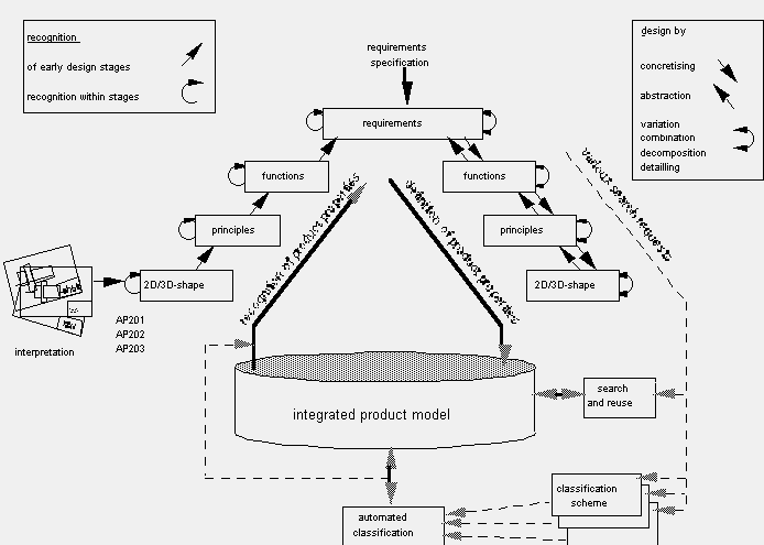
Main requirement for an efficient computer-aided re-use of existing design solutions is a product developing system, that integrates computer-aided design in all life-cycles and allows the integration of information from recognition. Recognition is necessary, when information is not suitable for usage with computers or incomplete in a sense of phase-oriented product-development. The concept of automated classification with the goal of recognition of product properties and compression of information based on standardised product databases ensures the unified recognition and interpretation of stored information (fig. 3.1).
 Figure
3.1: Architecture for finding existing design solutions
The user-conform adaptation of unexploited information in order to use it in actual or future product development is of great interest for every enterprise. Most subtasks of new design tasks have been solved earlier, documented and saved on special media. Many representations of such solutions are available only in paper-form. One assumes that in the USA less than 15 % of all engineering drawings used were constructed using CAD-systems (fig. 3.2).
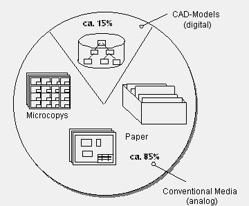
Figure 3.2: Ratio of digital model-data to conventional data /Möse-95/
Many of todayës enterprises digitalize their drawing archives and store them in form of pixel- or vector-drawings. A suitable form for supplying this information is not known yet /GrRL-96/. Paper drawings and microcopys have one thing in common: They are analog. In comparison, the world of the computer is digital. Thanks to the rapid development in plotter technology it becomes faster to get analog information out of digital CAD-data. A drawing constructed by a CAD-system can be put to paper immediately. Vice versa, changing analog drawings into 2D or 3D CAD-models is laborious and connected with loss of information.
Existing approaches for information recognition of technical drawings contain a separation of the whole changing process in three main stages: Digitalization, image analysis and semantic interpretation (fig. 3.3). These stages are processed more or less automatic in the different approaches. State of the technology in terms of drawing recognition is a partly automatic interpretation with the possibility of interactive correction /Liu-94/. This approach automatically processes only the digitalization. Within the stage of image analysis, some mechanisms for an automated processing of special tasks are realised. The higher a goal of interpretation is, the more difficult is the automation. A general solution for an automated processing of all stages is not yet available.
Figure 3.3: Process steps for recognition of drawings and their realisation
A general goal of a system for automated classification is to automate the formerly manual or computer-aided processed activities for encoding parts. Therefore methods are needed, that can prepare existing or in the future created information for a user-conform early recognition of product properties and classification. The concepts to develop have to be able to release the designer from classifying parts manually or partly automated in a way, that the designer can extract specific product properties and classify them at a certain state of product development. Thereby one can create complex product properties or classification characteristics using product properties of an early state of design that can be used for searching or forming part families before the design is finished. The automated recognition of product properties that accompanies the design and development and the resulting classification can be seen as a part of an integrated approach for using information of integrated product-models.
Considering the formulated requests, in the following a system for 3D drawing-recognition will be presented (fig. 4.1). The system is designed in a way, that it can handle different 2D-representations for single parts as an input. These are:
Figure 4.1: System architecture for information recognition
To handle technical drawings in paper-form they have to be scanned first. After the vectorization of the pixel-data, the image recognition methods determine elements, converts them in the 2D-data-interface and makes them available for the 3D-interpretation. For the recognition of sketches also a more intensive image recognition is necessary first. The resulting data is also converted in the 2D-data-interface. The data determined through image recognition can also be converted into 2D-model-data if necessary and so be available for processing a 2D-CAD-System. For the input of 2D-model-data only a model-data-converting in the 2D-data-interface is necessary.
The processing scheme for input, interpretation and recognition of drawings is shown in fig. 4.2. At first a drawing is digitalized with a scanner. Thereby, it is split into many single pixels. When the pixel data is available in a correct, binary form, the vectorization begins. Its aim is to describe the pixel-representation through vector set, e.g. lines and polygons.
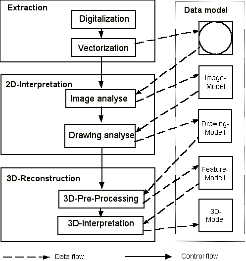
Figure 4.2: Processing scheme of the model changing
Within the image analysis the vector data is abstracted and analysed. The goal of this is the exact recognition of geometric elements, symbols and texts. This is the requirement for the semantic interpretation of the drawing, the steps for the image analysis contain the vector pre-processing, the element recognition and the element standardisation.
The main subject of the vector pre-processing is the removal of faults and the completion of vectorized data. These two steps contribute the necessary data reduction without loosing relevant information. The subject of element recognition is to recognise the geometric standard elements like lines, circles, arcs and freehand-lines from the vector data, that was resolved within the vector pre-processing. This step uses pattern-definition, pattern-extraction and pattern-comparison. After finishing the element recognition, the scanned drawing is available in form of arranged geometric elements. An element standardisation can rearrange the position and orientation of the recognised elements, because the digitalisation, vectorization and element recognition may have caused some inaccuracies.
The image analysis delivers geometric elements. These elements can be used by CAD-systems, but they havenët the semantics of CAD-drawings. The drawing analysis deals with the semantic interpretation of the image data based on drawing standards. Main subjects are the recognition of annotation information in the drawing, recognition of graphical symbols, separation of shapes and annotation lines, recognition of dimension graphs, arranging of the views and recognition of views and sections.
In the first phase all section representations have to be recognised from the drawing data. This recognition also uses pattern definition, pattern extraction and pattern comparison. The recognition of dimensions is realised using three steps - the extraction of the dimension elements, the identification of dimensioned shapes and the structuring of the recognised elements in a dimension graph. At the end of this process each drawing element should be defined with a dimension or implicit with the type of geometric element. This is realised with a connecting of a dimension with its geometry. In the fourth phase the drawing data is grouped in views and sections. The complete recognition can only be realised with the geometric shapes, because geometric annotation elements (e.g. the axis of symmetry, center lines) are connected with the shapes.
The complete reconstructing process for the 3-D recognition consists of three main steps: 3D pre-processing, 3D interpretation and verification of the reconstructed models. The 3D pre-processing consists of four steps: The first step of view standardisation contains the transformation of the coordinates and their assignment to the projection planes. The transformation of the coordinates changes all global coordinates into local ones of each view. In the second step all existing straight and angled sections are positioned. Their position results from an analysis of the views. Therefore, a transformation of the coordinates is also necessary. In the third step the assignment of the half-sections, local sections and details is processed. For example, a half-section is separated using the axis of symmetry, are mirrored into two separated representations and finally completed by laying on top of each other. The fourth and last step separates each views in one outmost contour, isolated shapes and remaining lines.
After the 3D pre-processing the 3D-recognition itself starts with a 3D-interpretation. The process starts with generating so-called half-spaces from 2D-data. Starting at these generated half-spaces, the topological elements and their data are reconstructed successively. The generating of the half-spaces is model-controlled and data-driven. The first thing is trying to generate a half-space, while analysing a 2D-line and using neighboured, already generated half-spaces. When this is impossible, the half-space generating is done hypothetical, (e. g. plain or cylindrical half-spaces) with a following verification or falsification. In case of a falsification a new half-spaces is generated, using the information of the last verification. This procedure creates a complete 3D-geometric model.
An automated classification of products builds upon the information of integrated product-models and therefore ensures the consistency of all information that is generated during the product development. Results of recognition-processes can also be used for classifying tasks. The concept of an automated recognition of product properties as a request for searching for existing design solutions leads to a system architecture, whose central component is a integrated product model /GrMH-95/. Based on this, CAx-Systems can create information along the process of product development on the one side and evaluate stored information for classification on the other side (fig. 5.1).
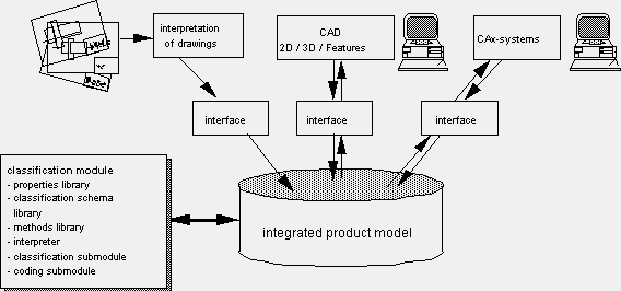
Figure 5.1: System-architecture with classification-module for an automated classification of products
The integrated model contains the logically defined and semantically correct representation of all information relevant for a product, that means requirements, functions, principles and shape. With this, all product characteristics are available as model instances. Thereby, it is of no relevance for the product properties extraction, which CAx-System generated the information e.g. recognition or interpretation procedures. Essential is the consistent adaptation and interpretation in accordance with the obligatory product model scheme. A main aspect of this is that classifications represent product properties respectively connections of properties that can be generated depending on the properties representation and the extraction methods used. The strategy for automated classification consists of the use of declarative knowledge for properties representation in a product model and the adapted and problem-oriented methods and process structures for extracting specific classification-keys from these representations.
A main request for the methodical product property extraction is the way properties are represented in the product model. This is based on a layer-concept, which allows structural relationships of all product properties to product-representations and life-cycle-stages (fig. 5.2).
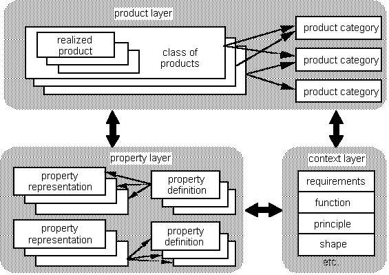
Figure 5.2: Layers of the property-representation
The main concept of the classification module (fig. 5.1, left side), which processes the automated product property extraction and the following classification, is a strictly modular structure. This modularity is achieved with the development of structured, expandable libraries for product properties, classification schemes and algorithms. The functionality of the classification module is given by the algorithms supplied by the library which are adapted to the desired property extraction. The modularity and the flexible use of the classification module directs to its use within an efficient product development environment on one side or within a CAD-system with limited functionality (e.g. only geometric modelling) on the other side, where in this case only the limited information provided by this system can be used for classification.
An expansion of this approach is the design accompanying classification. It is based on the same principles as the formerly described. A design accompanying classification expands the functionality in a way, that during the design process the classification module can be used as an assistant. Depending on already stored and therefore incomplete information all temporary possible product properties are extracted or put in a concrete form in dialogue with the user. This functionality is reached by decision-structures within the mechanisms for evaluation of properties or property structures.
The results of the automated classification can be processed directly or stored within the integrated product model with associations to the product representation (fig. 5.3). This concept allows the usage of the extracted results from the property extraction and classification for an entirely feedback to support the product development and production.

Figure 5.3: Classification results and related products
The extracted product properties respectively part code (e.g. encoded by text or numbers) can be used afterwards as:
Following research in the area of drawing recognition has to concentrate on the extraction of annotation information from drawings, because this is the only way to use existing know-how entirely. This can be the interpretation and extraction of dimensions, tolerances and surface-information, technological information, text-fields or form feature elements.
Another main focus is the interpretation of drawing for assemblies. If this information would be available in a suitable form which CAD-systems can handle with, the principles and functions realised with the assemblies could be reconstructed. This would be of great interest for searching for existing solutions. Another use of recognition of drawing for assemblies could be the automatic generation of parts list.
In the area of automatic classification one could imagine the support of design process from a design-demon. It works in the background and tries permanently to find parts in the database, that are similar to the actual design task. The user gets information about the results and can use these parts, if they exist. This could help avoiding to design new objects in every part of the design process. If any data occurs that canët be used by the calssification module for an automated classification, one could imagine the invoking of special interpretation procedures or recognition procedures that are able to re-deliver the data in a useable form.
/Dirz-72/ Dirzus, E.: Reorganisation des Informationswesens bei integrierter Auftragsabwicklung in Maschinenbauunternehmen - Voraussetzungen, Planung, Durchführung. Dissertation, RWTH-Aachen, 1972.
/GrMH-95/ Grabowski, H.; Meis, E.;
Hain, K.: Integriertes Produkt- und Produktionsmodell.
In: Informationstechnik der technischen Informatik (it+ti), Heft 5, 1995.
/GrRL-96/ H. Grabowski, S. Rude, C.
Liu
Recognition of Engineering Information from Technical DrawingsTMCE Symposium,
Budapest, 1996.
/Hich-86/ Hichert, R.: Probleme der
Vielfalt.
Teil 2: Werkstatt-Technik 76, S.141-145, 1986.
Teil 3: Werkstatt-Technik 76, S.673-676, 1986.
/Liu-94/ B. Liu
Entwicklung einer Methode zur automatischen 2D/3D-Produktmodell-wandlungUniversität
Karlsruhe (TH), Dissertation, Shaker Verlag, 1994.
/Made-92/ Maderholz, R.: Umsetzung
von Benutzeranforderungen an die CAD-Normteiledatei - Funktionsgruppen,
Anwenderoberfläche, Auswahllogik.
In: Senk, G. (Hrsg.): Referatensammlung NormCAD 92, DIN e.V., Beuth, Berlin/Köln,
1992.
/Möse-95/ R. Mösel
Effizientere Nutzung von Altzeichnungen mit Hybrid-Systemen
CAD-CAM Report, Nr. 5 1995.
/Milb-91/ Milberg, J.: Wettbewerbsfaktor
Zeit in Produktionsunternehmen.
Münchner Kolloquium ´91 , Springer Verlag 1991.
Professor Hans Grabowski: Engineering School from 1951-1954, after then design engineer in various industrial companies. 1961-1965 studying mechanical engineering at the Technical University (RWTH) of Aachen. 1965-1969 design engineer in industry. 1969-1974 scientific researcher and chief engineer at the Machine Tool Labratory (WZL) Aachen. Since 1975 director of the Department for Computer Application in Planning and Design (Institut für Rechneranwendung in Planung und Konstruktion, RPK) at the Faculty of Mechanical Engineering of the University of Karlsruhe and additionally director of the FZI (Forschungszentrum Informatik) since 1983 (head of the research group CAD/CAM). Since 1989 Dr. h.c. from the University of Budapest/Hungary. His main research interests are CAD system development, product models, modelling techniques, standard parts, interfaces, data exchange, computer graphics, engineering databases and intelligent CAD.
Stefan Rude received his diploma from the faculty of the mechanical engineering at the Karlsruhe University in 1985. Since 1985 he is working at the RPK in numerous ESPRIT, governmental and industrial projects. Representative in CAM-I´s Geometric and Product Modelling Program, in VDI´s activities on finding engineering design solutions in terms of function, physics, material and shape. He received his doctor degree in 1991. Since 1993 he is chief engineer at the RPK. He is active for STEP, ESPRIT, governmental and industrial research on CAD/CAM and teaches about "knowledge based design systems".
Chenguang Liu received his B.S. in Xian Jiaotong University, P.R. China, in 1982 and M.S. in Mechanical Engineering at University of Karlsruhe, Germany, in 1993. He is currently a research assistant at RPK, University of Karlsruhe, Germany. His research interests include pattern recognition, fuzzy engineering, object-oriented modelling and product data exchange.
Karl Hain received his diploma from the faculty of the mechanical engineering at the Clausthal University in 1986. After then he worked as a design engineer in industry. He is currently a research assistant at RPK, University of Karlsruhe, Germany. His research interests are the development of integrated product models, product data exchange and automated classification of products.