Strategies for
Product Knowledge Management and
Feedback to Design - Application
Examples
Prof. Dr.-Ing. Peter Dietz,
Dipl.-Ing. Steffen Penschke,Dipl.-Inform. Andreas Ort
Technical
University of Clausthal, Institute for Mechanical Engineering(IMW),
Germany
1 Introduction
The work with design support systems is basically
initiatedby the need to assure competitiveness in the future for
manufacturing enterprises.Many competitive factors have to be taken into
consideration in connectionwith market behaviour, product types,
production volumes, specialisationetc. In general product costs, product
quality and the delivery at theright time are the key factors. The
pressure to shorten the time to marketfor new products and therefore to
shorten developement time requires anadequate use of know how possessed by
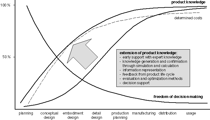
a company. The designer with hisdecisions is responsible for 70 to 80% of
product costs, since materials,manufacturing methods or usage properties
are more or less determined inthis phase. Therefore the product quality
increasingly depends on the qualityof decision making at the design
stage.
In manufacturing enterprises the
product knowledge isdistributed across the whole company. This know how
represents an essentialresource for successful competition in the market
and should thereforebe preserved and used as efficiently as possible. A
way of reaching thisgoal exists in the use of knowledge based systems
which contain accumulatedproduct knowledge on different aspects during the
product life cycle (e.g.design, manufacturing, usage, recycling). Besides,
product data modellingand management has become more and more an important
feature for enterprisesto strengthen their competitive
position.

fig. 1.1: Extension of product
knowledge throughthe use of information technology (following
[KrHJ_94])
This paper will identify
major strategies on how productknowledge can be used during design and how
it can improve the qualityof a product. The resources used for this
analysis are European and nationalresearch projects (the IMW participated)
in the field of design, manufacturingand quality assurance. Taking their
field of research and their objectivesinto account, the developed
strategies will be extracted and analysed.In parallel, the application of
such results will be reviewed. Based onthis analysis, the impact and
gained efficiency will be described. Thiswill result in a perspective of
how such strategies and applications canimprove a product. The concluding
chapter will give an overview of possiblefuture strategies. These are
developed from existing approaches, makinguse of new technologies and
research results. The paper is written in themain perspective for possible
end users.
2 Application examples - a case study
Starting point for the case study
presented here was tocheck the possibilities for a harmonisation of
developed research prototypeswithin the IMW and to discover main goals for
future work. The followingchapters will give an analysis of projects,
research prototypes includingshort descriptions, especially focused on
handled product knowledge andaspects of design
support.
2.1 PICASSO (Practical and Intelligent CADfor Assembly Objects)
The focus of PICASSO
[picasso_96] was the developmentof a design methodology and a supporting
CAD tool that makes informationon tolerances, machine components, process
tools etc. available to thedesigner and leads him through the design
process. This system was applied,at first, in the design of plastic spray
moulding and press tools. PICASSOoffers the designer a choice of assembly
types (classes) and leads himthrough the design, component by component.
As each part is chosen, itconstrains the choice of subsequent components,
so that at each stage,fewer decisions are required of the designer. The
PICASSO system consistsof a component definition module (allowing a
catalogue of components tobe defined), an assembly definition module
(allowing a database of assemblyclass definitions to be defined, including
rules constraining the way inwhich components fit together), an assembly
design module (allowing a particularinstance of a class of assembly to be
designed), and a functional tolerancemodule (determining tolerances
automatically from component function anddistributing tolerances between
mating parts).
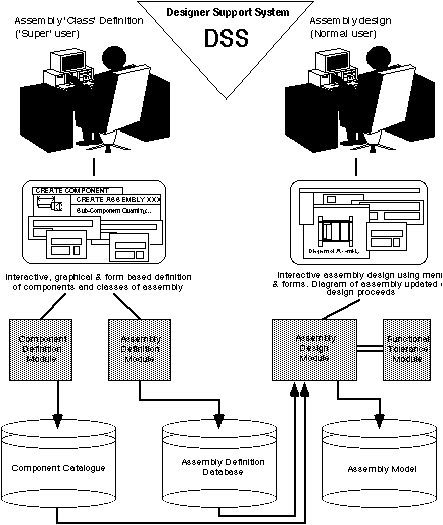
fig. 2.1: Concept for PICASSO
system
The PICASSO assembly design
methodology has two distinctphases, assembly definition and
assembly design. The firstphase represents the tailoring of a
general design system to the specificneeds of a company or application
area. This work occurs only once fora particular company or application
area - once the assembly definitionshave been created, they only need to
be altered if a completely new typeor class of assembly is to be built by
the company. The first phase involvesthe definition of all components and
types or classes of assembly to beused. Classes of components are
represented by a parameterised geometrydefinition, together with a set of
non geometric attributes if appropriate.Classes of assemblies are
represented by a list of component classes andquantities, together with a
set of rules which constrain the way in whichcomponents may be used within
that class of assembly. Component classesand assembly classes may be
abstract or non-abstract. An abstract classis not fully defined; it exists
merely to classify or group together aset of subclasses and cannot be
instanciated.
The second phase is the
actual design of assemblies tobe built, and uses the prototype design
system, together with a libraryof assembly definitions created during the
first phase. This phase involvesa user choosing an abstract class of
assembly, and using this as a templateto design a non-abstract class of
assembly. When all component classeswithin the assembly have been fully
specified (are non-abstract/makable/buyable)then the assembly is also non
abstract and can be manufactured. When choosingthe actual components to be
used in an assembly, the user is presentedwith a menu of choices from the
catalogue. This menu only contains componentswhich will sensibly fit with
components already specified in the assembly.This is achieved via the set
of rules specified as part of the assemblytemplate definition. Once
chosen, each component is automatically placedinto the assembly model in
the correct position with respect to other
components.
The main information handled
by the system are tolerances(according to ISO 286) and knowledge about how
mould components are assembled.They are represented in rules and formulae.
The functional tolerancemodule represents the whole ISO 286. The
assembly design modulerepresents all information concerning
geometry and relationships of components.This module is used to check if
and how components fit together and alsohow they fit together in a
assembly (mould). A super user, the designerand in few cases the
manufacturer, must feed the system gradually (stepby step). The system is
used during embodiment and detailed design.
The software was built up in C++. The knowledge is
totallyincorporated by the CAD system. Only the funcional tolerance module
(ISO286) was programmed as a module which can be placed in any other
software.During the project about 14000 parts and about 4200 rules of
moulds wereadapted to the PICASSO system. By this large number of parts it
was recognizedthat the system slowed down extensively. Every time one
component was chosen,the system started to scan all introduced rules to
trace all possible waysin which the mould could be built up into the next
step. After the project,this problem was solved with a new algorithm.
2.2 EQUIP (Work Methodology for Development ofQuiet Products)
To achieve the low noise levels imposed by the evolvingEuropean
and national regulations, current practice in traditional industriesoften
consists of searching for ad hoc solutions at the prototype stageof
product development. This trouble shooting and search for solutionsis
mainly achieved by specialists in acoustics. The main objective of
theEQUIP project was to provide the designer with a consulting system to
obtainlow noise products from well conducted design [equip_97]. A work
methodologyand tools for industry were developed, that will enable
manufacturers toreduce noise levels, time to market, development and
material costs. Theproducts of companies involved were earthmoving
machines, cooling equipment,heating and airconditioning systems and
municipal vehicles.
Following a detailed
analysis of present industrial practicefor noise reduction, the
methodology, consulting system and measurementmethods to be developed were
applied to the low noise design of real prototypeproducts with the aim of
reducing their noise levels by 3-10 dB(A). A specializedmethodology for
low noise design was developed based on general methodologyand on a
thorough assessment of industrial needs. One task was to get
knowledgeabout the information flow concerning noise control in the design
processand to indentify what kind of information is needed, exchanged and
created.Software and a knowledge base that support the methodology were
developed.The knowledge base was partly filled with data available from
the industrialpartners during the project. Missing measurement methods for
acquiringdata that is essential for the low noise design process were
developedand applied.
Main achievements
are the development of an approach fordesigning low noise products, the
establishing of a model for this approach(SADT), the definition of
necessary information for each step of designinglow noise products, the
characterization of the usage of the model forsoftware definition, the
definition of libraries for different kinds ofknowledge (e.g.
requirements, solids and fluids properties, measurementmethods, component
instances, formulae) and the definition of views tocomponents. An approach
of creation of noise path models was developedand successfully tested. A
way to propose and select suitable noise controlmeasures was determined. A
method for the elaboration of acoustic requirementsfor a machine has been
built up. Several design examples and design approacheswere mapped on the
EQUIP approach in order to check its applicability.The design of new
products as well as the noise control of existing productswas
considered.
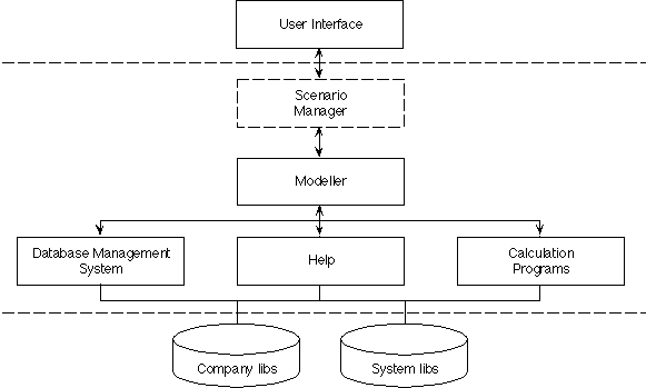
fig. 2.2: Concept for EQUIP
system
The developed system can be
updated and customised forbranch specific applications, i.e. there are
default system librariesand branch specific company
libraries. The modeller is amajor part of the system and
provides the functionality for a componentbased noise path modelling,
calculations, visualisation of result (e.g.noise level ranking and sound
power spectra for several components) andoptimisation of a model. It is
possible to build up a noise path modelby instanciating components, noise
generation mechanisms, receivers andlinks. The scenario manager
consists of a visualiser and an executionmechanism. It is an independent
program that is intended to help the userbuild and examine noise path
models. Scenarios could be created by manualwriting, system logging of
user actions or generation from graphical processschema (like SADT
models). A scenario is a script like description whichallows the scenario
manager to provide guidance to a designer in performinga complex task.
Tasks come in two forms. One is that of executing anotherscenario (called
subscenario). Another manifestation of a task is a program,module or
function that can be executed directly. Therefore a scenarioconsists of a
number of tasks and conditions (pre- and postconditions).The precondition
must be satisfied before the scenario is allowed to berun. The
postcondition is satisfied upon successful completion of a scenario.By
means of preconditions it is possible to set the constraints withinwhich a
designer can operate. Within these boundaries the ordering of scenariosand
subscenarios gives the designer guidence on how to manoeuver throughthis
space.
The tools and methods developed
were to be validated bythe design departments of the companies involved in
the project and appliedto the products mentioned, thereby achieving the
noise level reductionsrequired.
2.3 PLUS (Parts Libraries Usage andSupply)
The portability of parts libraries is a major
economicconcern for CAD system users, component manufacturers and for CAD
systemvendors. To allow such portability a whole set of concepts, known as
theP-LIB approach, has been developed in Europe. This set of concepts is
basedon the experiences gained using proprietary solutions and/or national
standardsthat fulfilled only portions of the end users needs. The
objectives ofthis project were to validate, possibly improve the P-LIB
approach andprovoke the practical use of this approach through a complete
set of pre-industrialtools as well as contribute to the final
standardization work through demonstrationof the concepts, preparation of
pre-normative specifications as input toEuropean and international
standardization.
Parts libraries allow
the definition and description ofparts for the design of products. Using a
standardized description format,the concept enables the comparability and
exchange of parts. Through thestructured description of parts and
sophisticated search strategies duringembodiment design the selection of
repeated parts will be made easier.Moreover, the standard allows a
multi-supplier search, i.e. the searchfor parts in various supplier
catalogues. The focus is the embodiment designwith respect to repeated
parts (costs).
Main results of the
project were the development of threepre-competitive library management
systems which support the new capabilitiesresulting from the P-LIB
approach and the migration from previous proprietaryor standardized
systems, the development of a partial description of thecomponents of a
part supplier and the development of a practical know-howabout the P-LIB
approach among the project partners. These results makeit possible to
demonstrate the interactive generation of a part library,the exchange and
automatic integration of this library by library managementsystems related
to different CAD systems [DiOr_96]. A parts library systemis connected to
a CAD system and will serve as a parts catalogue. Partscan be selected and
inserted into the current design. Such systems alsoallow the
representation of the part hierarchies. But special tools, suchas
converter or managment tools, are hardly available.
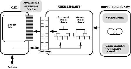
fig. 2.3: Concept for part libraries
The theoretical background is, that parts are orderedin a tree
hierarchy and defined by properties (applied to each node inthe
hierarchy). The approach makes use of object oriented concepts. Thedata
itself is represented as entities and relations. The model is describedin
EXPRESS. Some of the data is already available in a former
standard[din_4000] format which can be converted with some effort.
However, a goodchunk of information is missing and has to be added
interactively. Thefunctionality of part libraries will be used mainly
during embodiment anddetail design.
The
data structures can cope with the highly complex organizeddata, but the
approach of managing the data requires deep knowledge andmay not result in
best performance. Most of the work will result from theupdate and adaption
process from existing data. This will result in majorchanges for available
system architectures. The applicability and the efficiencyof the approach
has still to be proved.
2.4 AMANIS (Advanced Manufacturing InformationSystem for the Designer)
The aim of the research project
AMANIS was the developmentof an approach which allows the collection and
preparation of current company-specificmanufacturing information as well
as to provide this information to thedesigner in a convenient way
[amanis_95]. Based on this provided manufacturingexperience, the
manufacturing properties of future designed products shouldbecome more
transparent. The designer should be able to obtain efficientdecision
support for the optimisation of products from the manufacturingpoint of
view. AMANIS was focused on metal removing manufacturing
processes.
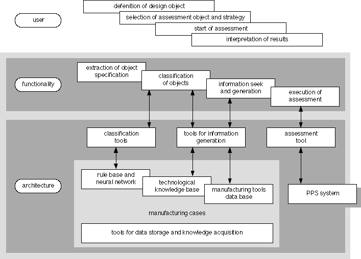
fig. 2.4: Concept for
manufacturing informationsystem for the
designer
The main information handled
in the system are manufacturingtimes, costs and problematic events to be
expected during manufacturing.Knowledge about optimised and actually used
NC-programs are collected bymanufacturing data collection systems and
represented as tables representingmanufacturing cases. The system is used
during embodiment and detail design.Developed tools for knowledge
management and representation are NC-Analyzersfor the extraction of
relevant information from NC-programs, a tool forthe induction and
representation of NC-sequencing rules based on algorithmfor autonomous
knowledge acquisition, a manufacturing-oriented featurerecognition tool
based on algorithm for autonomous knowledge acquisitionand a
manufacturing-oriented CAD-model classifier based on neural
networktechniques. The tools are integrated within the CAD-system
Pro/Engineerfor extraction of relevant CAD-information from part and
feature modelsin order to both populate the case base and reason about
newly designedpart and feature models.
In general, the practical experience gained in the projectwas,
that techniques for autonomous knowledge acquisition can help to reducethe
efforts during creation and administration of knowledge bases. However,the
training and subsequent unsupervised knowledge acquisition requiresa lot
of consistent cases. Adaptations to new situations are carried outwith a
certain time gap. As far as AMANIS is concerned, the case base
mainlyrepresents information from a dynamic and unstable environment which
resultsin reduced reliability of the provided information to the designer
whois not able to interpret the results with respect to their
correctness.Techniques for autonomous knowledge acquisition should only be
used forthe representation of timely invariant and stable information.
2.5 QCIM-PM (Quality through CIM - ProductModel) - Registration and analysis of requirements
Within the QCIM project the IMW
developed a prototypetool for the capture and analysis of requirements in
the design process.This tool is based on an integrated product model to
support quality managementin product design. The product model was
developed in the national germanproject Quality through CIM (QCIM). Main
aim of the tool named demandais the handling and visulization of
complex, multidimensional requirementstructures and interrelations to
support the designer in the early phasesof the design with the reuse of
already existing knowledge from all phasesof the product life
cycle.
Demanda uses the ECCO
Toolkit [StMa_96] for theimplemention of the QCIM product model and the
standard data exchange.The QCIM product model handles information from all
phases of the designprocess. Requirements, functions, solution principles
and geometric informationare fully integrated and can be weighted.
Therefore, when the designerdefines a requirement he can access already
existing weighted solutionsstored in the product model. One speciality of
the model is the concurrenthandling of the actual design requirements for
a specific product and thesolutions already in the database. The product
model does not only captureone set of requirements but the whole series of
dynamic changes to therequirements which represent the flow of the ongoing
design.
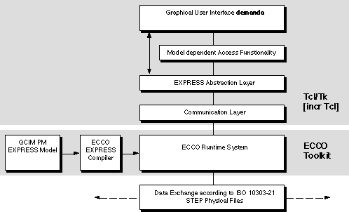
fig. 2.5: Implementation concept
for demanda
Knowledge is stored in
several facettes in the productmodel. Requirements are defined by their
properties. These properties tendto be unprecise in the beginning of the
design and get redefined in thelater design stages. Properties can be
stored as a textual descriptionor as mathematical expression. The
interrelationships provided knowledgeabout the interactions between two
requirements. They can be interpretedas simple Ñif -- then rulesì. The
most importent knowledge stored in theproduct model are the definitions.
Definitions in the product model arethe super class of all entities in the
design process namely requirements,functions, solution principles and
geometry. The weighted definitions supportthe designer in his
decisions.
The main goal in implementing
demanda was to testthe theoretical approach of multidimensional
requirement structures andrelations. One main insight was that the
designer does not think in theway that the product model handles the data.
Therefore the designer hasto be supported by the user interface when
structuring the requirements.The requirement interrelationship is a major
problem, since the designeris seldom aware of these often conflicting
interrelationships. This problemcan only be solved by two means. Either
the database consists of the productrelevent requirements and their
interrelationships (collected by a knowledgeengineer) or either by the use
of an automated procedure to check the requirementproperties or a hybrid
approach. At the time of writing all informationis processed manually.
Further research will focus especially on the automateddetection of
interrelationships.
2.6 Sheet metal design for manufacturing
The special research
project `processing of sheet metal'(SFB 362) is a common project with the
University of Hannover under theleadership of the technical University of
Clausthal. Aim of the projectis to investigate the basic material and
technological processes of formingand joining of sheet metal. The project
is organised in three groups. Thefirst group deals with material
properties and the flow of material duringdifferent forming and joining
operations. Aim of the second group is torecover optimal parameters for
processing of sheet metal from the technologicaland organisational point
of view. The third group works on sheet metalpart properties such as
stability and resistance.
The IMW is
working on a subproject ësheet metal designí[DiPO_97]. Aim is the
development of basic design methodologies for sheetmetal products to meet
the requirements of function and manufacturing.Problems the project deals
with are the adaptation of requirements andfunctions to consider
geometrical restrictions depending on material propertiesand processing
parameters in early stages of the design process as wellas the
possibilities to structure and describe technological information.After
several analyses of practical sheet metal use concerning products,design
processes and manufacturing technologies the main information wasextracted
and systematised. Different criteria for an efficient supportof sheet
metal design processes were recognised. Information on materialsand
manufacturing that determine geometrical parameters must be realisedif
possible in early phases of the design process for a further
consideration.Therefore material and technological information must be
represented adequatelyto support the transition from product planning and
conceptual design toembodiment and detail design. The representation of
such information shouldpermit an interactive optimisation of geometric
parameters with regardto material and manufacturing.
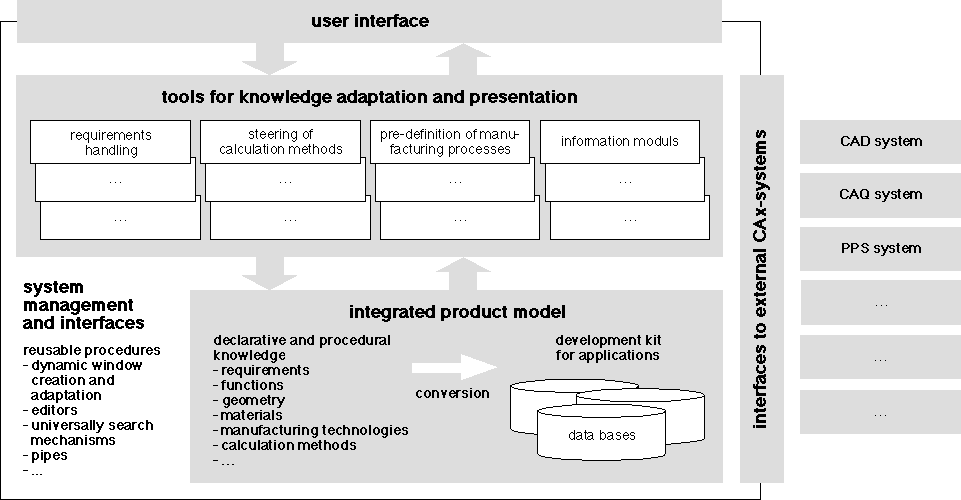
fig. 2.6: Concept for
sheet metal informationsystem
The
developed system concept is characterised by severallayers such as the
integrated product model containing all data describingthe product with
declarative and procedural knowledge (e.g. requirements,geometry,
materials, manufacturing technologies or calculation methods)and the tools
for knowledge adaptation and presentation. A tool for
requirementshandling allows the designer to register requirements
in textual formand to convert these requirements into references or
constraints on desiredor required product properties (e.g. preferred
materials, manufacturingtechnologies, machines or geometries). The
steering mechanisms for calculationmethods allows an administration
of formulae, their solution in allfeasible directions and their use
according to the design progress by meansof priorities. A tool for
pre-definition of manufacturing processesallows an interactive
optimisation of geometrical, material and manufacturingparameters for deep
drawing processes. The designer can set parametersor choose them from
referenced requirements. Undetermined parameters willbe calculated if
possible.
During the product planning the
system provides the possibilityto specify requirements for a new sheet
metal part to be developed. Bymeans of editors and search mechanisms the
designer will be supported inconversion of requirements into references or
constraints. During embodimentand detail design a pre-definition of
manufacturing processes will be supported.Main goal is to define a sheet
metal part that meets the requirements andthat is optimal in the view of
manufacturing. Therefore the validity ofreferenced requirements will be
checked during the pre-definition process.For instance: if various drawing
presses are are preferred, the systemchecks the manufacturability of the
part by means of the individual presses.The results of these checking
processes will be visualised in a suitableway. As a result the designer
has not only specified the geometry of thepart but also bound possible
materials and manufacturing processes
andmachines.
The main goal in
implementing the information system wasto test the developed design for
manufacturing approach. The data basewas filled with some test records. In
general the approach was useful.One insight was, that the designer reaches
an optimum dependent on hisindividual experiences. There is no methodical
help like optimisation strategiesor similar. Further research will focus
especially on the provision ofa higher semantic level through a feature
based approach to support methodicaloperating and on the recovery of
manufacturing experiencies to supportparticularly the determination of
tolerances.
3 Analysis of handled engineering knowledge
The goal of using
information systems as described aboveis to get a high quality product at
the lowest price and in shortest time.The designer should be supported to
make qualified decisions on the basisof reliable information or provided
with answers on questions that ariseat the design stage of product
development. The described systems are focusedon small domains of certain
disciplines, e.g. a design support system forthe assembling of moulds, a
manufacturing information system for metalremoving processes or a
information system for pre-definiton of deep drawingprocesses. The range
of systems varies from ësimpleí, specific knowledgebased systems (used in
one specific phase of design) to complex, self acquisitioningknowledge
based system with active feedback from later product life
cyclephases.
The first aim in analysing these systems is to reuse experiencesgained in the projects, i.e. concerning information modelling, applicabilityand usefulness of developed approaches. This includes the reuse of informationmodels or parts of the models and of system components or specific tools.A second aim consists in a detection of general strategies for provision,processing and use of product knowledge during the design stage for a capabledecision support. From this result two considerable tasks:
3.1 Systematisation of engineering knowledge
There is a multitude of exertions dealing with the problemof
systematisation of knowledge in general and especially of
engineeringknowledge. For instance each research on design object
representation canbe regarded more or less as an effort to systematise
design knowledge.Therfore the following small survey could surely not be
complete. In generalall of these efforts represent different views on the
problem, taking severalaspects into account.
One important point of view may be human memory structuresand
psychological interrelationships in problem solving. So the
cognitivestructure of a human distinguishes in two fields, the
epistemicand the heuristic structure [Dörn_79]. The
first contains asystem of categories to structure the knowledge about
facts and applicableoperators. It determines the capability to solve tasks
reproductively.The second structure represents a library of procedures
(methods) for problemsolving, i.e. a system of meta or inside operators to
build operators.It will be used if no solving method is retrievable
immediately. Furthermorethe memory structure may be interpreted as a kind
of semantic network whosenodes represent contents and whose connections
are relations between thecontents. A human has the opportunity to detect,
use and build specificrelations such as
concrete-abstract-relations, whole-part-relationsor
space-time-relations. In order to systematise engineering
knowledgethis approach seems to be too abstract. Nevertheless, it is
useful to supportinformation modelling and structuring of knowledge bases
analogously tothe human memory.
Another
point of view is from the field of artificialintelligence (AI)
[Görz_93]. Resulting from this are a number of distinctionsconcerning
knowledge. A first is to differentiate data (e.g. a,b, c, 100, 2),
information (e.g. a = 2, b = 100) and knowledge(e.g. c = a *
b). A second distinction follows the general subdivisionof AI systems into
three broad categories [Nils_82]. The knowledge abouta problem domain that
is represented in a global database is called declarativeknowledge.
It would include specific facts like data and relationsbetween the data.
The knowledge about a problem that is represented ina set of rules is
called procedural knowledge. It would includegeneral information
that allows a manipulation of the declarative knowledge.The knowledge of a
problem that is represented by a control strategy iscalled control
knowledge. It includes a variety of processes, strategiesand
structures used to coordinate the entire problem solving process.
Elsewhere[Pham_91] the kernel of intelligent knowledge based systems
should consitsof a knowledge base containing knowledge about a problem
domain (e.g. facts,information, rules of judgement; also called
domain) and an inferencemechanism for manipulating the stored
knowledge to produce solutions toproblems (also known as inference engine,
control structure or reasoningmechanism; also called task). Ideally
domain and task are independent.Concerning the most popular ways of
knowledge representation a third distinctionis possible. Therefore one can
differentiate into rule-based (knowledgein terms of facts and rules
for manipulating facts), frame-based(a frame, concept, schema or
unit as a recordlike structure, a form forencoding on a stereotyped
situation; associated with a frame is a set ofattributes, the descriptions
or values of which are contained in slots)and semantic net-based
(semantic nets are similar to frames; itis a network or graph of nodes
linked together by arcs, arcs representrelations) representations.
Meanwhile case and rule bases are sometimescalled shallow knowledge
in contrast to schemes using frames, semanticnets, graphs or modells which
are called deep knowledge.
In addition there are several efforts to systematise knowledgefrom the engineering domain. Following an analysis of main sub-activitiesin design [LeAl_89] introduces a division of engineering knowledge into:
The information handling behaviour of the designer couldbe another criteria for knowledge systematisation. To observe empiric experimentsa framework for describing informational behaviour is presented in [BaLe_94].To classify so called information fragments serveral definitions are made:
In order to build very large knowledge bases (VLKB) forintelligent CAD (ICAD) in [Yosh_93] the necessity for a knowledge standardis emphasised. There is a given classification of knowledge in two dimensions:
Tacit knowledge could be explicitly or implicitly recognisedby human beings and used for reasoning but very difficult to describe (e.g.the so called commonsense). Codified knowledge is always recognised anddescribed with symbols, figures and so on (e.g. textbook knowledge, informationstored in a database). Expertise and skill are mostly composed of unrecognisedand tacit knowledge. Unrecognised and codified knowledge is meaningless.The primary goal of systematisation of knowledge should be to convert recognisedand tacit knowledge to recognised and codified knowledge to make it computableand improve its reusing and sharing. Besides two types of design knowledgeare identified:
A
design process begins with ambiguous or rough descriptionsof the design
object and they will be gradually detailed and
completed.
Stemming from the field of feature modelling a matrixrepresentation for product description is known [Webe_96]. So a featureshould be defined in the scope of a specific view onto the product descriptionwith respect to:
A
view describes the way to look at the productand its properties
during the product life cycle. In some disciplines thereare similar, but
not quite identical frameworks for product life cycledefinition. Anyway,
in practise each product has to follow its own
lifecycle.
The selection of exertions above shows that it is notvery easy to systematise knowledge. It seems to be almost impossible tostructure knowledge in a uniform manner. The method of systematisationstrongly depends on the view of the problem. Nevertheless several similaritiesare recognisable. More or less there is a subdivision of knowledge concerning:
In compliance with the various approaches it seems tous that the matrix representation considering product propertiesand life cycle is quite suitable to represent engineering knowledgehandled in the systems as described in chapter 2 (tab.3.1). In thisway we could describe mainly the content of information concerning theproduct and the usage of system functionality with regard to each stageof design/developement.
tab. 3.1: Description of handled engineeringknowledge with
respect to information content and
usage during life cycle (scheme
following [Webe_96])
((1) - PICASSO, (2) - EQUIP, (3) - PLUS, (4) - AMANIS, (5) - demanda, (6)- sheet metal design)
| product life cycle product property classes | marketing | product planning | conceptual design | embodiment design | detail design | production planning | production | ... |
| requirements | (2)(5)(6) | (1)(2)(5)(6) | (1)(2)(5)(6) | (1)(5)(6) | (5) | (5) | ||
| functions | (2) | (2) | ||||||
| solution principles | (2) | (2) | ||||||
| geometry | (6) | (1)(3)(6) | (1)(3)(6) | |||||
| tolerances | (1)(3) | (1)(3) | ||||||
| materials | (6) | (3)(6) | (3)(6) | |||||
| manufacturing methods and parameters | (6) | (4)(6) | (4)(6) | (4) | (4) | |||
| strength and durability | (3) | (3) | ||||||
| costs | (1)(3)(4) | (1)(3)(4) | (4) | (4) | ||||
| time | (4) | (4) | (4) | (4) | ||||
| usage properties | (2) | (2) | (2)(3) | (2)(3) | (2) | |||
| environmental properties | (3) | (3) |
Making use of a matrix
representation, the scope of theproject applications can be neatly
represented. The table indicates clearlythe main field of application. It
seems that the major need for supportlies in the embodiment and the
detailed design phase. The heavy loadedvertical axis of the product
property class requirements shows theimportance of an integrated
requirement management.
Another aspect of knowledge systematisation may be thedesign science [HuEd_96, PaBe_93]. From this we tried to derive a kindof `sophistication level' of possible design support. Certainly this levelmatches with different representation forms of knowledge. Concerning thecomplexity of engineering knowledge it may be devided into (tab. 3.2):
Simple knowledge is represented as
plain structured datawhereas complexity grows with relationships such as
rules or formulae upto interactively working (system) processes triggered
by design activities.Main points are structured data descriptions, rules
and functions. Allof the systems are able to handle such information.
Analysis methods areslightly underrepresent because there are a lot of
powerful applicationson engineering problems (e.g. FEM systems,
calculation programs for variousmechanical components, tools for kinematic
simulation) that are not partof the systems itself. There seems, however
to be a lack of applicationsconcerning process oriented
information.
tab. 3.2: Complexity of handled knowledge (legendas in tab. 3.1)
description | processes |
One more representation supplement the reflection. Inour opinion
temporal behaviour of knowledge is also an important aspecton knowledge
characterisation. The durability of knowledge in terms oftime means the
amount of changes that take place on the data the systemis fed with.
Durable means that once the data is inserted, it willnot change
anymore (i.e. lifespan of several years, e.g. bearing calculationmethod,
general guidelines for embodiment design such as designing to allowfor
expansion, standards and regulations) and can be used unreflected
(premisingthat it is correct) in this state. Unsettled means that
the dataunderlies permanent change (i.e. lifespan of several days, e.g.
capacityutilisation, occupation of machines, stock information) and that
the useof it depends highly on the time. We used a scale from one to five
to roughlycharacterise the data used in the systems of each project
(tab3.3).The spearhead unambiguously lies on durable information.
Certainly onehad to ask how useful is a design support with unsettled
information. Butnowadays due to concurrent engineering approaches and a
production in aturbulent environment unsettled information become more and
more of interestfor a support of development
processes.
tab. 3.3: Temporal durability of handled knowledge(legend as in tab. 3.1)
durable (static) | unsettled (dynamic) |
The last
two tables show that most of the projects handlerather static data and
stick to a more simple representation of knowledge.This is naturally due
to the enormous degree of complexity one has to handlewith more
sophisticated systems. However, this analysis shows in whichdirection
further research should head, i.e. systems which can handle moretime
critical data (as a major requirement form the industry) and withit
naturally more complex information structures and support
activities.
3.2 Knowledge feedback strategies to design
From our experience we
have observed that design supportrelies mainly on feedback information,
i.e. information from a later lifecycle phase of a product back to the
early stages of a new one. Operationsperformed in one phase of the product
will surely have impact on laterphases and the product itself. The
different systems showed various aspectsof the feedback which will be
elaborated in this chapter.
In the
beginning, when a product is developed from scratch,ideally no experience
at all exists for this product. The designer willenter each phase of the
development trying to make optimal decisions forthe future. Only when a
phase is finished or the product is already inuse and when he observes
possible drawbacks in the handling of his product,he may be able to
connect those drawbacks (the symptom) to decisions insome phases (the
cause) he had made. This process is purely manualbased on designers
own experiences since the system itself does not knowor recognise anything
of these interrelationships, i.e. none feedback(fig. 3.1
top).
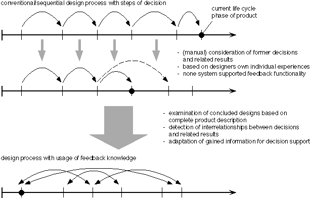
fig. 3.1: Knowledge feedback to
design
Having products with a more or
less complete product description,the designer is able to extract such
interrelationships manually and touse them when he is going to make
improvements to his products or to createnew products, i.e. using the
experience and knowledge of already concludeddesigns. In this case he is
able to profit from feedback in far earlierphases. Still, this is a manual
process and that is the reason we callit quasi feedback. This
means, that the designer could use descriptionsof concluded designs but
there is no intelligent retrieval to detect suchinterrelationships.
Therefore the nearest goal is to build up such retrievalmechanisms. So the
designer could search for situations similar to hiscurrent stage (e.g.
products with comparable properties, information ona specific life cycle
phase). He can look after related results, i.e. possiblesolution for his
problem. Thatís why we call it feedback with manualadaptation.
Moreover a next step may be to dedect possible interrelationshipsbetween
decisions and related results by the system itself, i.e. a
moresophisticated support to deduct support actions from arising design
contexts.Relationships between experience and decisions taken before shall
be extractedautomatically such as it is done intutively by human beings.
The designerthere will have the opportunity to select either one or more
of the proposedsupport actions to discover the most suitable one. It might
also be thathe will go another way in problem solving. As a consequence he
must havethe possibility to go (model interactively) such a new way
(case). We callthis feedback with automatic-interactive adaptation
(fig. 3.1bottom). Still using this mechanism, but in a strictly
automated form,may be another strategy. This means preventing the designer
from makingdecisions. The most suitable solution/action will be detected
and initiatedby the system. Here we speak of feedback with
automatic-autonomous adaptation.This may be a disputable strategy. It
might however be useful, e.g. ina strongly bounded (high-complex) domain
the designer has neither experiencesnor reliable information. In our
opinion this should be the exception.Having said that, we would like to
stress the point, that automatic deductionshall not be used to take
decisions but only to indicate possible interrelationshipsand solutions.
This is to keep the power of deciding clearly in the handsof the designer.
It can not be the goal to exclude him from any step ofthe
design.
tab. 3.4: Kind of adaptation of knowledge -feedback strategies (legend as in tab. 3.1)
manual adaptation | automatic-interactive adaptation | automatic-autonomous adaptation |
Summarising the analysed
projects from the viewpoint offeedback it is clear that most of them have
only manual or quasi feedback(tab 3.4). In practise this is to feed
a data model with the moreor less formalised experience and to make use of
it during the design phases.However one system strive for more and we
think that this will be the directionto go for in the
future.
4 Conclusions
This paper has introduced a
selection of design supportrelevant project run at the IMW. From that, an
analysis of knowledge engineeringwithin these projects has been made. This
included the knowledge representationand modelling and the strategies how
to make use of this knowledge forthe sake of design support. Although this
examination is largely an internalone, we believe that the applied methods
and the gained abstraction holdfor more than these projects. In this
sense, we like to summarise as follows(statements to think about when
building a design support system):
Relieving a designer in the way of taking odd and everrepeating
actions away from him means to model what in his mind is representedin an
epistemic structure. This is to model certain data structures whichwill be
matches with arising cases during the design and, in cases of fits,pre
described actions could take place. This structure is rather static.(The
odd thing about it is, that the modelled knowledge itself is originallya
procedural knowledge which appears for modelling as a declarative
andstatic one.) A more sophisticated support is to deduct support
actionsfrom arising design contexts or at least give the possibility to
describe/modelinteractively such new cases. Here, a meta-model is needed
and the systemhas to cope with the heuristic structure of the user. This
view on knowledgerepresentation, i.e. the view which takes care of the
human memory structures,indicates the level of modelling and the
complexity of application a systemdesigner has to think
about.
As already pointed out in previous
chapters, several feedbackstrategies have been extracted. The simple use
of documented data, themore advanced research in structured data and the
extraction of relationshipsfrom the set of existing data and the set of
(already) taken decisions.It is evident that future research has to
concentrate on those systemswhich model information beyond simple data
structures. Of interest arecomplex relationships which allow precise
reductions of the solution spaceto be made (refer to [Fric_96], tactics
during the search for solutions- balanced
search).
A design support system has to
accept decisions takenby a designer (and might be allowed to propose
solutions as well). It isstate of the art to document what decision has
been made (every simpleprogram and tool has an undo functionality). Not
that often, but stillcommon is to document, how something was decided.
This is derived fromthe decision itself and its context. It seems more
important to us to documentnot only what (design object) and how (design
process) but also why somethinghas been decided. This can be partly
reasoned from the underlying requirements.Still, design is a creative
process and some decisions might be arbitrary.It is important to document
them because they are the ones to be reconsideredfirst in cases of
unsatisfaction. Documenting why something has been decidedis also
important for possible feedback strategies to make design
processescomprehensible.
The analysis
seems to show a weighting towards of researchfor support systems
concerning the embodiment and detailed design phase.This is also reflected
in the overwhelming market for design tools whichexactly concentrate on
those phases (CAD systems and supplementing modules).On the other hand,
two important gaps have shown up. One is the missingsupport of the
planning and conceptual phase. The other is the missingextraction of
information from the later phases. The sentence already impliesthe aim. We
see the early phases still as a information target while thelater phases
are a source of them. In this paper we want to concentrateon the design
(instead of the manufacturing, use and replacement) of aproduct. Further
research should head into the direction of making useof as much
information as possible to support decisions in the very earlyphases of a
design. The information sources used for current support systemsseems to
be rather static and research concentrates on these. Actually,more
unsettled data is more important, because this data is the criticaltype in
terms of actuality, time, costs and so forth. This means, thatfuture
support systems should be nearer to such data and have to reflectchanges
of the data to the designer. He might be forced to revisit hisdecisions
then.
It is clear that stand alone
solutions will not servethe designers needs, if he wants to have access to
all relevant informationfor a sound product development. This implies the
existence of an integrationplatform (e.g. [DaPo_96] from the application
point of view). On this platforminformation of various characters are
located and shifted around for thepurpose of being accessed from any point
during the design process. Oneapproach is to have an integrated product
data model and to create viewsupon this model. Each view represents a
specific selection window whichgathers all necessary information for a
certain need of access. Once apart of data is selected (creating an
instance or occurrence), these instanceslack of their binding
relationships, i.e. the relationships which representthe dependencies of
all the selected data. We state, that the set of requirementsof a product
is a feasible and suitable set of relationships to hold allthe data pieces
together and that this (most unsettled) set can serve asan integration
platform for a design support system. Further research workhas to prove
this.
Moreover, a ënewí design support
system shall at leasthave those capabilities which the previous one had,
it should as well ofcourse provide more or better functionality. It shall
behave in the samemanner as the previous one and be used in the same way
Ð otherwiseit will not be accepted. Generally, this means that design
support systemsshould help the designer in the way he is working right
now, otherwiseit will be rejected. In contradiction to that, innovation
often requiresnew thinking and sometimes this new thinking (or
methodology) affects theusers. Although this paper is not primarily
concerned with this topic,we would like to point out, that a smooth and
sound user interface (followingresults of industrial sciences and
ergonomic studies) is a strict requirement.Otherwise all the finest and
best methodological approaches of knowledgeengineering are useless because
their benefits do not reach the user. Morespecifically, an accepted system
might be accepted as a tool but not asa support system. This means, that
it is used to perform some work, butthat all proposed advisory (or even
solutions) are rejected. This can haveseveral reasons but the main point
is, that a designer (as a human being)would not accept to be overruled by
a system. For this reason we wouldprefer the idea of proposing advice but
not the idea of automatic decisionmaking.
Literature
[amanis_95] N.N.: AMANIS - Advanced Manufacturing InformationSystem for the Designer. Project Brite-EuRam 5139, Contract BRE2-CT92-0158,Final Technical Report, AMANIS.CL.95.12
[BaLe_94] Baya, V. and Leifer, L. J.: A Study of theInformation Handling Behavior of Designers during Conceptual Design.T. K. Hight and F. Mistree (eds.): International Conference on Design Theoryand Methodology (DTM '94). Minneapolis 1994, DE-Vol. 68, American Societyof Mechanical Engineers (ASME), pp. 153-160
[DaPo_96] Dankwort, C. W. and Podehl, G.: IndustrialCAD/CAM Application and System Architecture - a Closed Loop. I. Horvathand K. Varadi (eds.): International Symposium on Tools and Methods forConcurrent Engineering (TMCE '96). Budapest 29-31 May 1996, pp. 206-211
[din_4000] DIN 4000: Sachmerkmal-Leisten. DeutschesInstitut für Normung (DIN), Berlin, 1981
[DiOr_96] Dietz, P. and Ort, A.: Verwendung von Wiederholteil-und Normteilkatalogen gemäß der ISO 13584 "Parts Library"unter besonderer Berücksichtigung der Anforderungen in der Konstruktion.VDI (ed.): Effiziente Anwendung und Weiterentwicklung von CAD/CAM-Technologien.München 22./23. Oktober 1996, VDI Berichte 1289, VDI Verlag, pp. 399-408
[DiPO_97] Dietz, P.; Penschke, S. and Ort, A.: Ansätzezur parallelen Gestaltung von Produkten und Fertigungsprozessen. VDI(ed.): Features verbessern die Produktentwicklung - Integration von Prozessketten.Berlin 20./21. Februar 1997, VDI Berichte 1322, VDI Verlag, pp. 313-329
[Dörn_79] Dörner, D.: Problemlösen alsInformationsverarbeitung. 2. Aufl., W. Kohlhammer Verlag Stuttgart,1979
[equip_97] N.N.: EQUIP - Work Methodology for Developmentof Quiet Products. Project Brite-EuRam 5983, Contract BRE2-CT92-0339,Final Technical Report, EQ-PR-Vj, Delft, 28 February 1997
[Fric_96] Fricke, G.: Successful Individual Approachesin Engineering Design. Research in Engineering Design 8 (1996) 3, pp.151-165
[Görz_93] Görz, G. (ed.): Einführungin die künstliche Intelligenz. Addison-Wesley Publishing CompanyBonn Paris Reading Massachusetts, 1993
[HuEd_96] Hubka, V. and Eder, W. E.: Design Science- Introduction to the Needs, Scope and Organization of Engineering DesignKnowledge. Springer Verlag Berlin Heidelberg New York, 1996
[KrHJ_94] Krause, F.-L.; Hayka, H. and Jansen, H.: Produktmodellierungals Basis für eine wettbewerbsfähige Produktentwicklung.J. Gausemeier (ed.): CAD '94 - Produktdatenmodellierung und Prozeßmodellierungals Grundlage neuer CAD-Systeme, Fachtagung der Gesellschaft für Informatik(GI). Paderborn 17./18. März 1994, Carl Hanser Verlag, pp. 29-54
[LeAl_89] Lenau, T. and Alting, L.: Intelligent SupportSystems for Product Design. Annals of the CIRP Vol. 38 (1989) 1, pp.163-166
[Nils_82] Nilsson, N. J.: Principles of ArtificialIntelligence. Springer Verlag Berlin Heidelberg New York, 1982
[PaBe_93] Pahl, G. and Beitz, W.: Konstruktionslehre- Methoden und Anwendung. 3., neubearb. u. erw. Aufl., Springer VerlagBerlin Heidelberg New York, 1993
[Pham_91] Pham, D. T. (ed.): Artificial Intelligencein Design. Series: A. Kusiak (ed.): Artificial Intelligence in Industry.Springer Verlag Berlin Heidelberg New York, 1991
[picasso_96] N.N.: PICASSO - Practical and IntelligentCAD for Assembly Objects. Project Brite-EuRam 5693, Contract BRE2-CT92-0273,Final Technical Report, Birmingham, November 1996
[StMa_96] Staub, G. and Maier, M.: ECCO Tool Kit ñUser Reference Manual. Institut für Rechneranwendung in der Konstruktion,Universität Karlsruhe (TH), Dokumentation, 1.1.3, Karlsruhe, 6.5.1996
[Webe_96] Weber, C.: What is a Feature and what isits use? - Results of FEMEX Working Group I. International Symposiumon Automotive Technology and Automotion (ISATA). Florence 1996, pp. 287-296
[Yosh_93] Yoshikawa, H.:
Systematization of DesignKnowledge. Annals of the CIRP Vol. 42
(1993) 1, pp. 131-135